8 Fluvial Landforms
Nahgeib Miller
Learning Objectives
After completing this chapter, you should be able to:
- Define what a stream is and describe its anatomy.
- Describe drainage patterns and networks.
- Explain the formation of gorges.
- Describe erosion by flowing water.
- Describe and explain how sediment is transported by flowing water.
- Explain and calculate stream discharge.
- Describe a stream geosystem.
8.1 Streams
Streams are any flowing body of water; however, the term river is reserved for the major branches of a stream system. The flow of a stream depends on gravity as a function of the slope, and as such depends on plate tectonics that drive uplift. Flow also depends on rainfall and the like, as determined by the climate. Furthermore, the amount of flow over the surface depends on the porosity and structure of the bedrock, as determined by its geology.
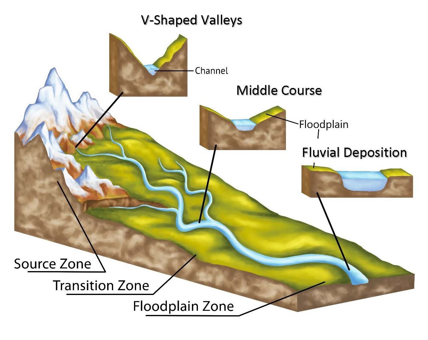
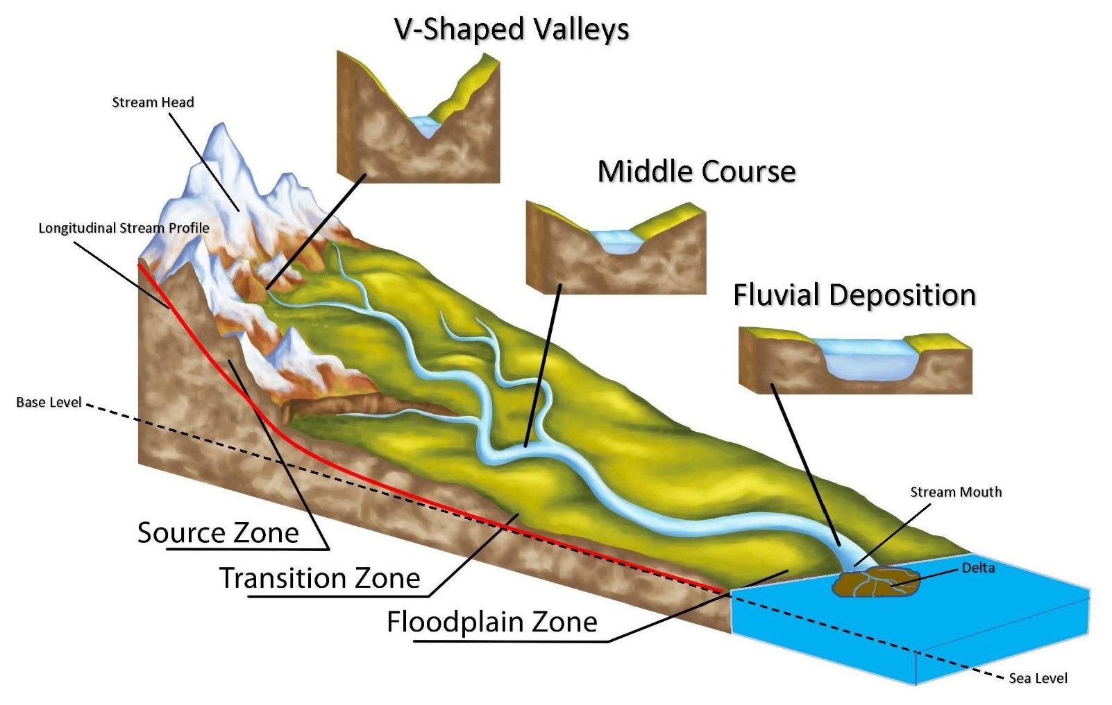
Looking at a stream in cross-section, three main components are visible: the valley, the floodplain, and the channel (Figure 8.1). The valley consists of the sloping areas around the stream and has the distinctive V shape. The floodplain is the area of low relief that is level with the top of the stream’s channel. The channel is essentially the bottom of the valley in which the stream flows.
When a stream carries a high sediment load and/or has a high velocity, it will flow in many channels at the same time (Figure 8.2). This is called a braided channel pattern.
Conversely, low-velocity/low-sediment-load streams will occupy one channel at a time and begin to meander (Figure 8.2). A meandering channel pattern is a positive feedback loop created when a stream in a straight channel pattern loses energy (because of, for example, a decrease in slope) and starts to develop a side-to-side motion in plan view. This creates alternating bends in the channel called meanders. The water travelling on the outside of the bend moves faster than the water travelling on the inside of the bend, leading to erosion of the banks on the outside curves and deposition on the inside curves. Therefore, the banks on the outside curve of a meander are called cutbanks and the banks on the inside curve are built up into point bars.
As the erosion along the cutbanks and the deposition along the point bars continues, it causes the “curviness” of the meander to increase, resulting in adjacent meanders’ growing closer together (Figure 8.2). During a flood, the stream can cut across the adjacent cutbanks, creating a cut-off meander. If the cut-off meander has water in it, it is called an oxbow lake.
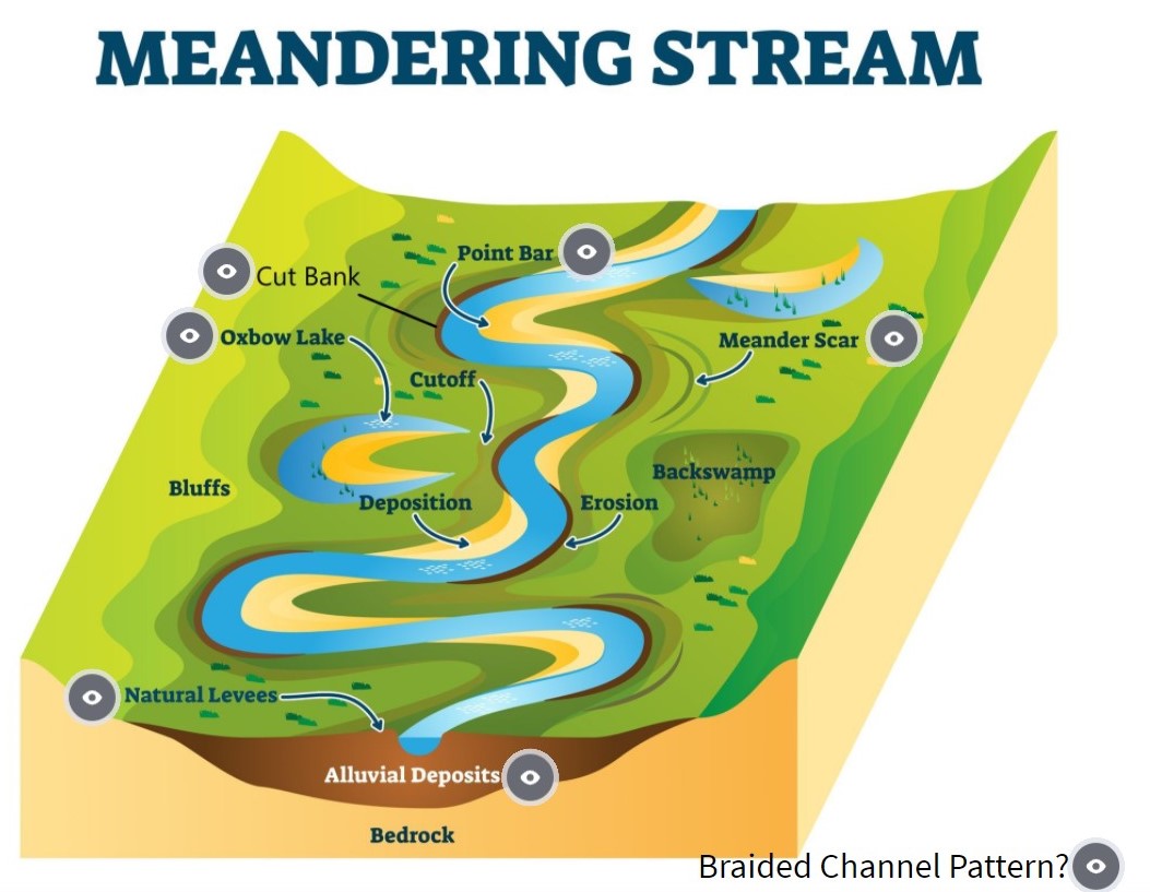
As previously stated, the floodplain is the flat part of the valley immediately adjacent to the channel. It consists of fine-grained sediment layers deposited by intermittent floods. During a flood, the water no longer flows in the channel; instead, it inundates the valley. Because the area the stream is spread over is very large, its velocity decreases significantly, allowing fine-grained material to be deposited (Animation 8.1). Most of the sediments are deposited along the border of the stream’s channel, building up into levees. These levees help to constrain the stream to the channel even during high flow between floods.

Click on the image to load the animation.
Drainage Patterns and Networks
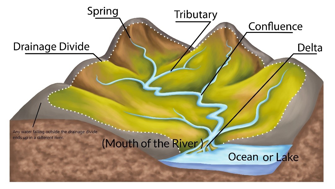
Drainage networks are contained within a drainage basin separated from other basins by drainage divides (Figure 8.3). Water that falls on land and flows over the surface in streams will eventually end up in one major channel called a river. All the water in a particular catchment basin will flow in streams, which will eventually become tributaries to the river. Water that falls in the same area but ends up in another river belongs to an entirely different catchment or drainage basin.
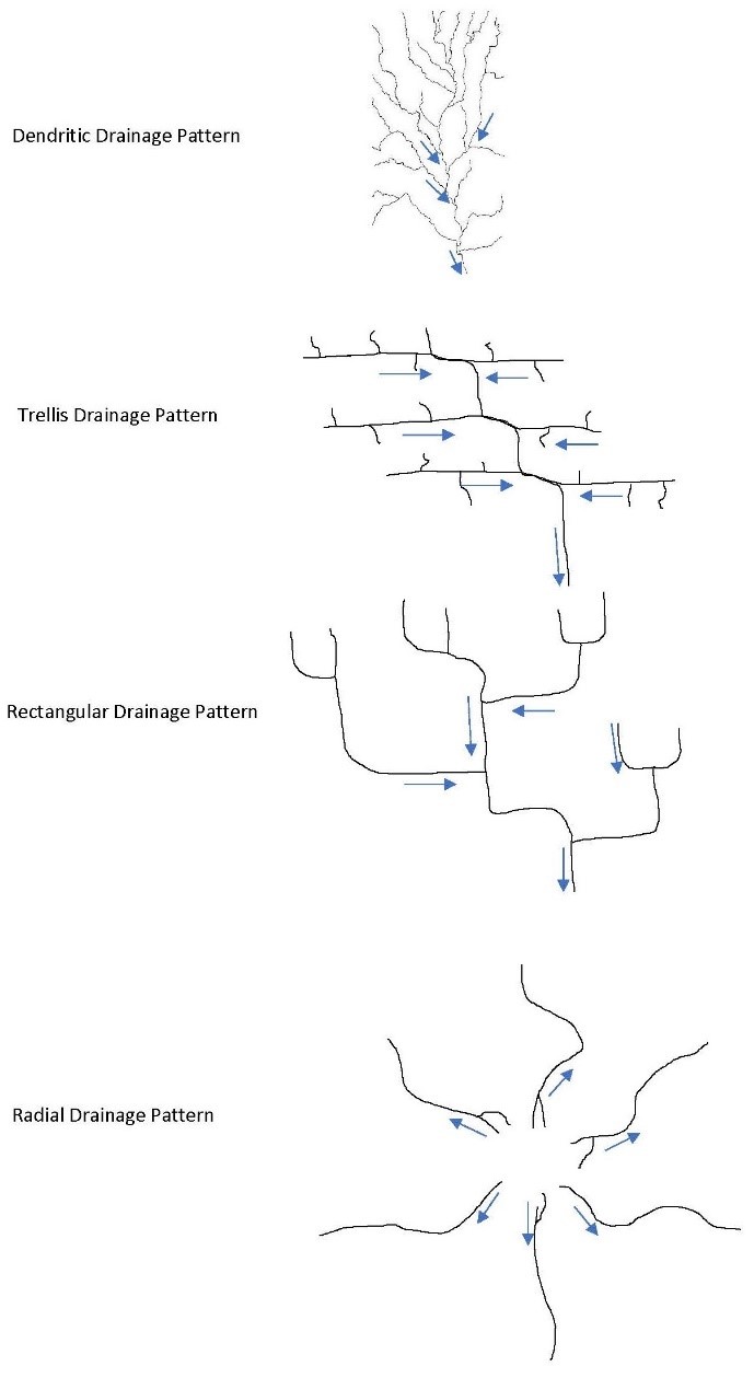
The pattern that the stream channels make as they move through the basin defines the drainage network as follows (Figure 8.4):
- Dendritic Drainage Dendritic drainage is characterized by a branching stream pattern. Just like branches of a tree joins the main trunk, so too do tributaries join the main “trunk” of a river.
- Trellis Drainage Trellis drainage develops on folded bedrock that exposes rocks with different rates of erosion, creating trunks and tributaries that are roughly parallel to each other.
- Rectangular Drainage Rectangular drainage develops on jointed bedrock that controls the direction of flow. Water travels the path of least resistance, and joints are natural linear zones of weakness in the bedrock. The joints, therefore, control the path of the tributaries and river. Because joints tend to have a rectangular pattern, the streams also have a rectangular morphology.
- Radial Drainage Radial drainage develops on domes or volcanoes that have a singular peak. All the streams flow away from the peak in all directions, yielding a radial pattern.
Drainage patterns are also influenced by the local geologic history. For example, the presence of a river in a gorge is evidence of previous uplift and was formed through either a superposed or an antecedent stream (Animation 8.2). A gorge is stream-cut through a localized mountainous region; however, if water follows the path of least resistance, why did the stream not flow around the uplifted rocks? How did it make its way to the top of the hill to cut it down into a gorge? Does water flow uphill?
Superposed streams develop on existing horizontal beds that overlie folded rocks. As the stream erodes through the horizontal beds, it is slowly brought in contact with the folded beds and eventually cuts a gorge through it. This is like lowering the river onto the top of the hill, the way you lower the blade of a circular saw into wood (Animation 8.2).
Antecedent streams develop on existing horizontal beds that are subsequently subjected to deformation and (relatively) uplifted through folding or faulting. As the folding slowly occurs, the stream is uplifted into the river and gradually cuts into the bedrock, like wood raised to meet a circular saw (Animation 8.2 and Figure 8.5) .
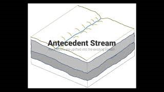
Click on the image to load the animation.
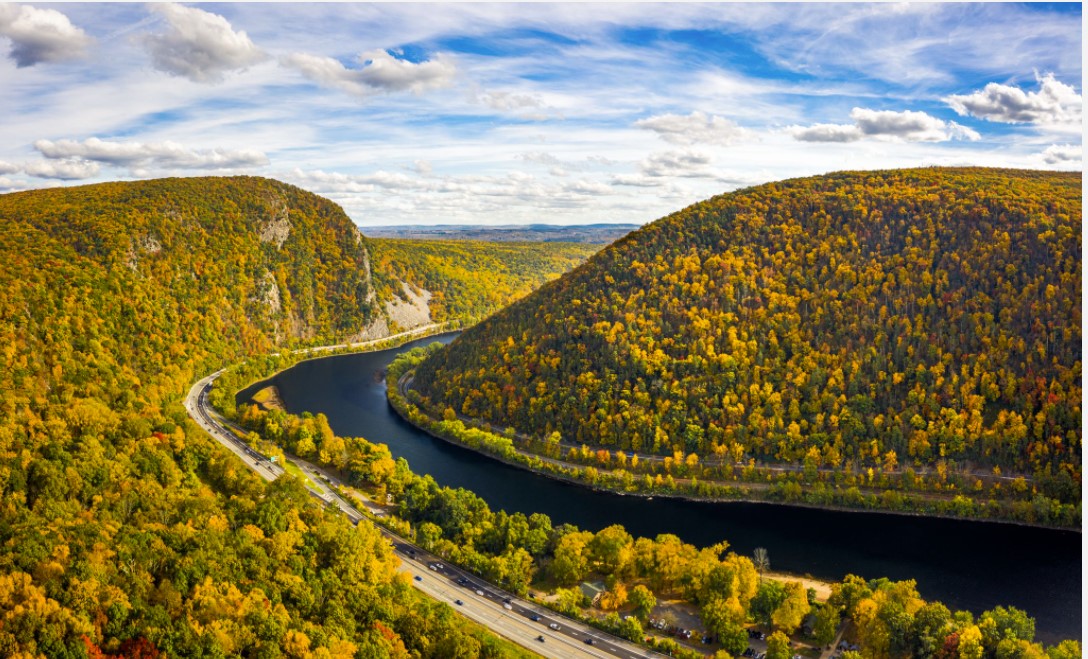
The Delaware River is an antecedent stream on the border of the U.S. states of New Jersey and Pennsylvania.
8.2 Erosion by Flowing Water
Even though water appears “soft” to us and gives little resistance when you immerse your hand, it is capable of reducing entire mountains to fine-grained sediments. Flowing water can erode solid rock through the following processes:
- Gullies Gullies are the beginnings of a channel in the head (start) of a stream. As water flows over the solid rock, indentations are created and constrain the flow, deepening the indentation into a gully (Figure 8.6).

- Headward Erosion In the headwaters, gullies are essentially nick points at which erosion by flowing water is activated. These nick points tend to migrate uphill toward the head of the stream. This migration is controlled by changes in the baseline of the stream, which causes re-energized headward erosion if it is lowered (Video 8.1).

Click on the image to load the video.
- Abrasion Flowing water will carry sediments with it as either suspended sediments or bedload. These sediments act like sandpaper, wearing away at the rock; this process is called abrasion. An example of abrasion is the creation of potholes in bedrock in a stream’s channel. Potholes are created when eddies in the water cause sediments to swirl against the bedrock, eventually carving out an indentation. The sediments come to rest in the indentation and move again when turbulent flow recreates the eddy. The progressive circular movement hollows out a pothole with sediments deposited in it.
8.3 Sediment Transport by Flowing Water
Water flows according to fluid dynamics with lamellar or turbulent flow (Figure 8.7). Fluids generally move in distinct segments, like individual threads in rope. Low-energy streams of water, like those on gently sloping terrains, will have laminar flow in which the individual water segments flow in gently waving parallel lines. When flow is more turbulent, like that of a high-energy stream on steeper slopes, these linear segments cross and mix with each other.
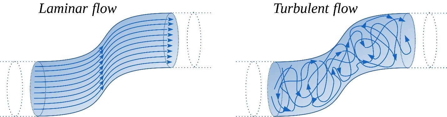
The factors controlling whether a stream will have laminar or turbulent flow are velocity, channel depth, and viscosity:
- Velocity When water moves faster, flow is more turbulent.
- Channel Depth As we will see in the Section 8.4), the depth of a channel affects the cross-sectional area of the stream, which in turn affects its velocity. Therefore, in general, the shallower the depth, the higher the velocity.
- Viscosity Viscosity is determined by the material that is dissolved and suspended in the water. The higher the viscosity, the greater the tendency toward laminar flow.
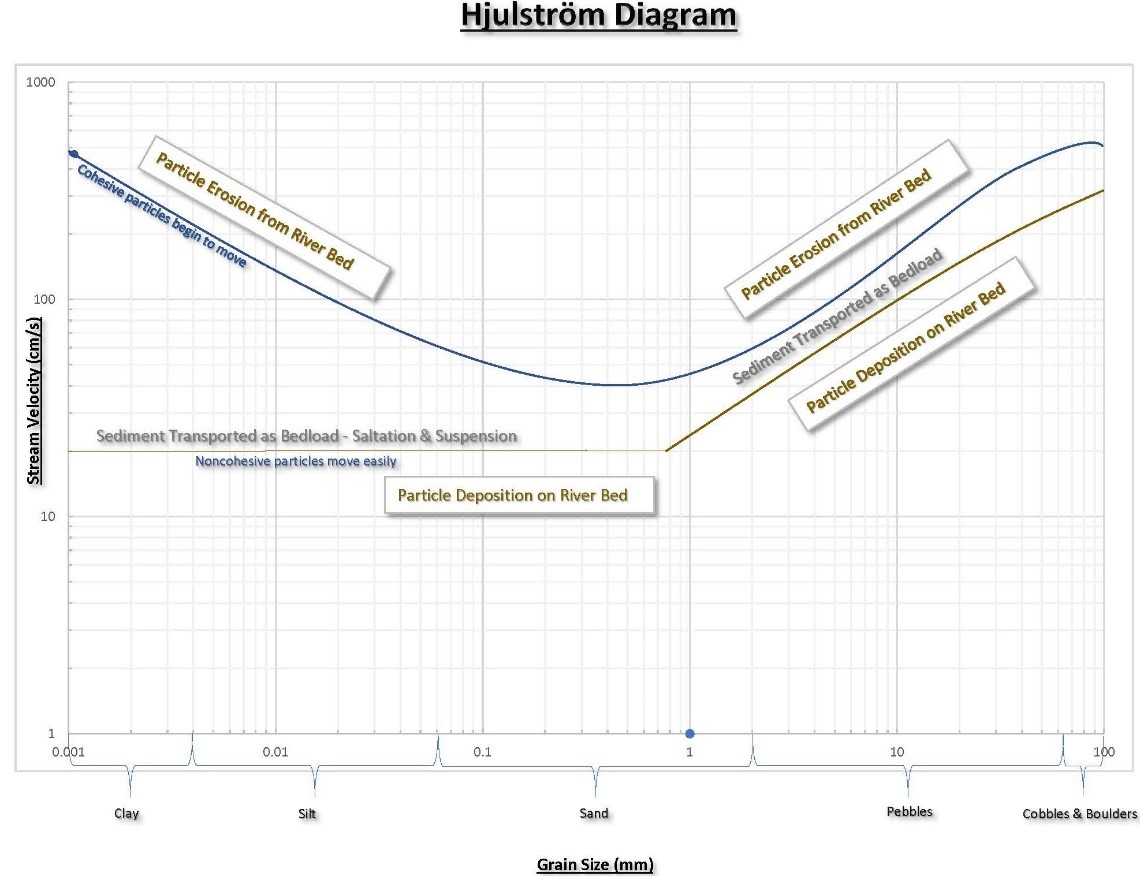
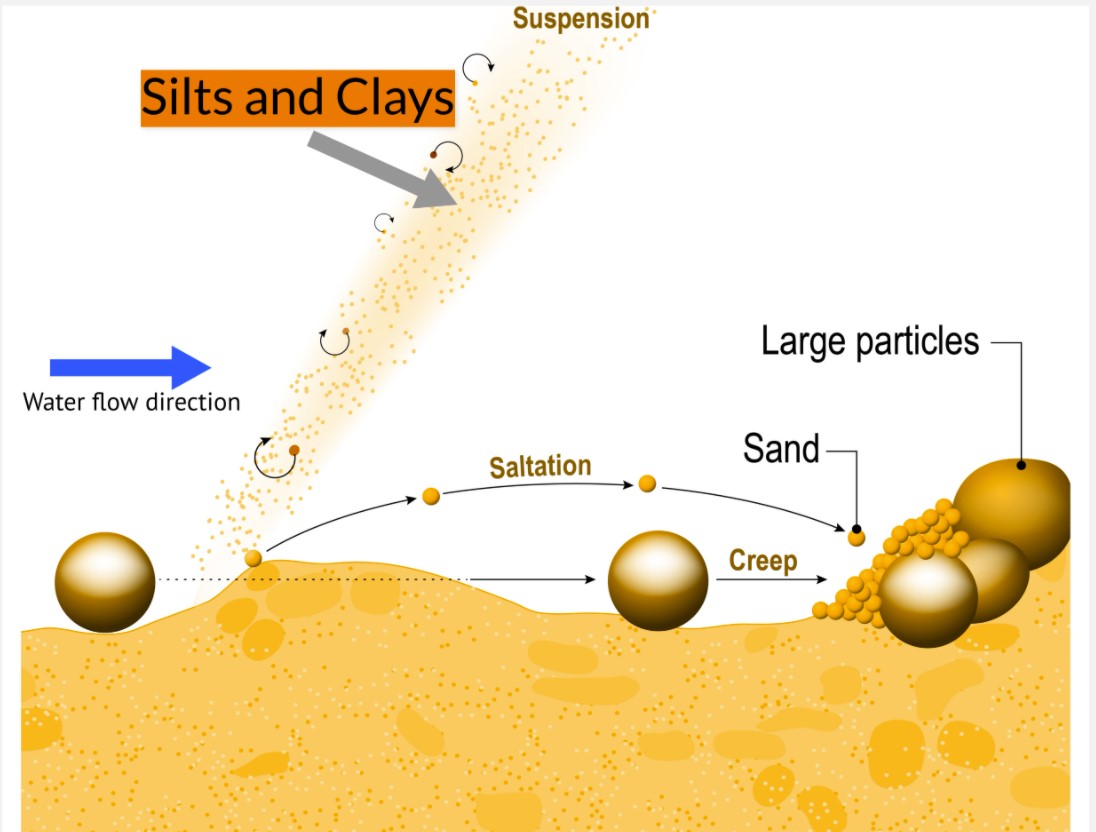
The sediment that is transported with the stream will be either suspended in the water column as suspended load or dragged along the base as bedload. More turbulent flows can sustain larger sediments in suspension; however, sand-sized sediments and smaller tend to travel as suspended load while gravels tend to travel as bedload (Figure 8.8). Note that during floods, streams can carry boulders as big as a house in suspension.
Bedload sediments are transported along the base of a stream by rolling, by being dragged, or by bouncing. Sediments that bounce will be in temporary suspension before settling out and returning to the base to be picked up again. This type of movement is called saltation (Animation 8.3).
Click on the image to load the animation.
The competence of a stream refers to the largest grain size that a stream can carry as either bedload or suspended load, while the total amount of sediments the stream can carry is its capacity. Competence and capacity are influenced by velocity and the volume of flow. Specifically, stream velocity influences competence and volume of flow influences capacity. However, a stream with high velocity will transport more sediment overall (it will have high capacity) than will a stream with low velocity.
Bedload Sediment Formations
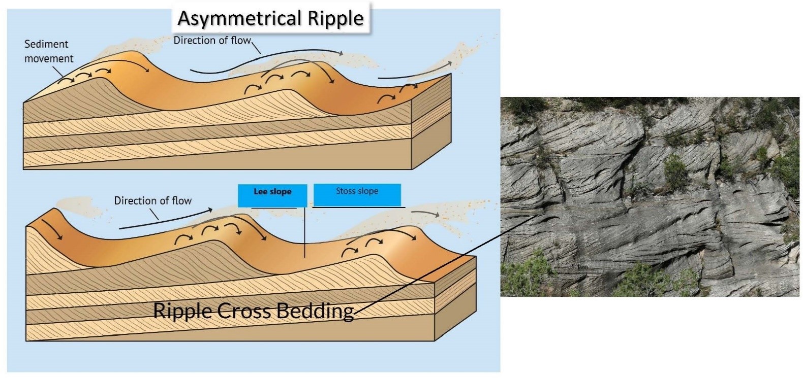
As sediments are transported along the base of the stream, they create distinctive formations related to their unidirectional movement. Specifically, ripples are formed at lower velocities, while dunes form at higher velocities. Ripples and dunes are asymmetrical humps in the bedload sediment, with the gently sloping convex slope (the stoss side) pointing upstream and the steeper concave (the lee side) pointing downstream. Ripples are of the order of centimetres in size, while dunes are of the order of metres in size.
Ripples and dunes seem to migrate along the bottom of the stream as the flow picks up sediment from the stoss side and deposits it on the lee side. As ripples migrate over previous ripples, the distinctive cross-bedding structure in a sectional profile is created. By examining the orientation of the lee side remnants in the cross-bedded profile, we can determine the direction of flow as well as its velocity, based on the size of the bedform (Figure 8.9).
8.4 A Systems Approach to Streams
Stream Discharge
Stream discharge refers to the amount of water that passes through a particular cross-sectional area per unit of time and is usually given in cubic metres per second. If you think of the stream as being like water passing through a hose into a bucket, the discharge is the volume of water that would end up in the bucket after one second. Therefore, we can state the discharge of a stream, Q, as the product of the cross-sectional area A and the stream velocity V. That is,
Q = A x V
If the amount of water in a stream system does not change, then the discharge will remain constant across any point along the stream. However, in reality there will be tributaries that introduce extra water to the system, increasing the discharge in the system thereafter. Due to this effect of tributaries adding water, a stream’s discharge tends to increase downstream.
It is important to understand a stream’s discharge because it does not change unless more water is added. This means that stretches of a stream between tributaries will have constant discharge, with a directly proportional relationship between the cross-sectional area and the velocity. That is, if the stream’s morphology changes such that the cross-sectional area decreases, then the velocity must increase to maintain the discharge. This results in the creation of rapids. When the converse, an increase in cross-sectional area, occurs, the velocity decreases — hence the old adage, “Still waters run deep.”
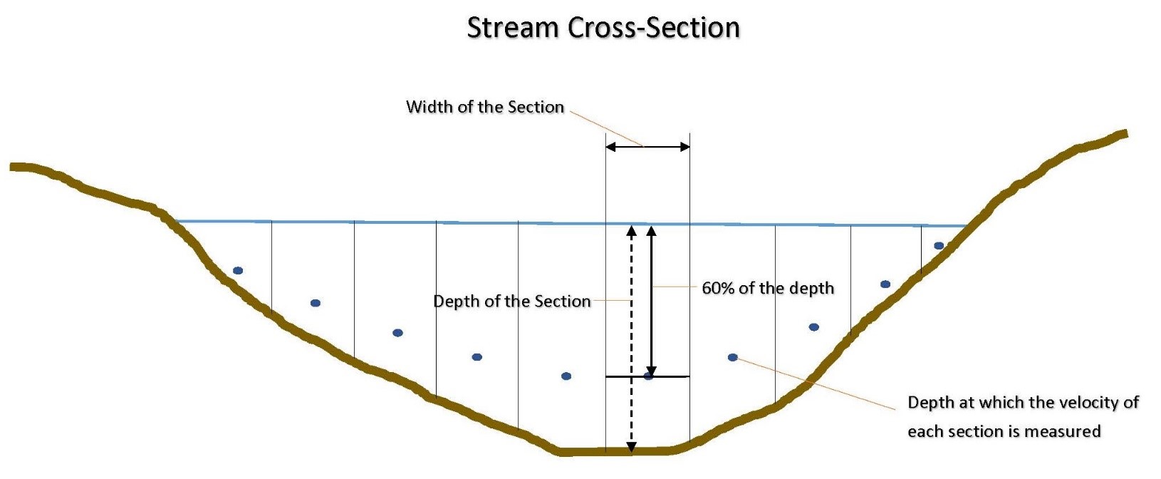
A river’s discharge can be estimated by dividing it into 5 to 10 sections perpendicular to its flow direction and applying the 0.6 rule. Creating more sections will increase the reliability of the results. The 0.6 rule states that the flow velocity of a river can be reliably approximated by the velocity at 0.6 times the depth of flow. A flow meter is usually used to measure the flow velocity at this depth at the centre of each section.
The discharge through each section is equal to the product of the area of each section (perpendicular to the flow, also called the cross–sectional area) and its mean velocity as estimated at 60% of the depth, that is, q = a × mean velocity. Therefore, the discharge of the river is the sum of the discharges through each section across the river (Figure 8.10).
Anatomy of a Stream Geosystem
A typical stream profile stretches from the headwaters in the mountains to the sea or lake (or inland, as for the Okavango River in Africa) and has concave morphology when in equilibrium. All streams try to achieve this stable profile by depositing sediments or eroding rock (Figure 8.11).
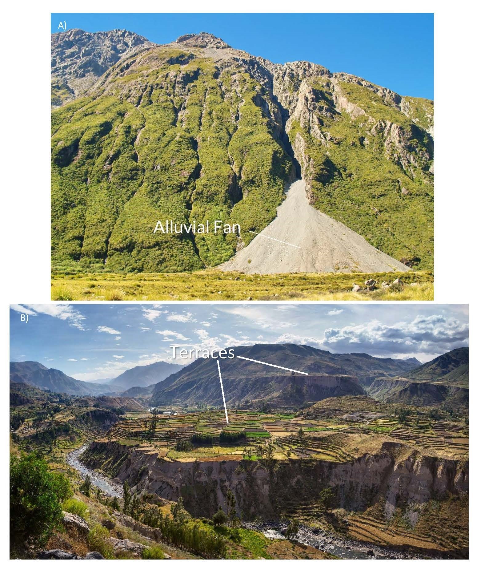
The river’s profile is steep at the head and almost flat at the mouth, which defines its base level (lowest point). Changes in the base level will affect the whole stream system because this is a major factor influencing equilibrium. Uplift can cause the base level to be elevated, resulting in more erosion upstream, while subsidence causing a lowering of the base level can result in deposition (Figure 8.12). For example, an abrupt change in the profile due to a lowering of the base level causes a change in grade (from steep to shallow slope), forcing the river to dump its sediments in an alluvial fan. When there is uplift, the base level rises, causing the river to cut deeper into its floodplain, creating terraces (Figure 8.12).
This is why dams on river systems that run across international borders are so contentious. A dam effectively raises the base level, causing deposition of sediment behind it in an alluvial fan and re-energizes erosion in the headwaters.
Flowing bodies of water
The major branch of a stream system
The sloping areas around a stream
The flat part of the valley immediately adjacent to the channel
Of a stream, flowing in many channels simultaneously
Alternating bends in a stream channel
The banks on the outside curves of a meander
The banks on the inside curves of a meander
A stream path across adjacent cutbanks
A cut-off meander containing water
Raised lines of deposited sediment constraining a stream to a channel
A branching waterflow pattern
A waterflow pattern of parallel trunks and tributaries
A rectangular waterflow pattern on jointed bedrock
A radial waterflow pattern away from the peak of a dome or volcano
A canyon or steep-walled valley cut by a stream through a mountainous region
Streams that develop on beds over folded rock
Streams that develop on beds that are then deformed and folded
The beginnings of stream channels in a rock indentation
Erosion of rock creating gullies that seem to migrate upstream in the headwaters
The wearing away of rock by sediments moving with the water
The repeated carrying and deposition of sediments by a stream
The measure of the largest size of rock particle a stream or glacier can carry
For streams, the total amount of sediments a stream can carry*combine with previous definition in same location
The shallowly sloped convex side of a bedload sediment formation
The steep concave side of a bedload sediment formation
The amount of water that passes through a particular cross-sectional area of a stream per unit of time
A system for approximating the velocity of flow of a river
A fan-shaped depositing of sediments create by an abrupt change, from steep to shallow, in a river’s profile
Flat elevated plains on either side of the stream’s channel and floodplain