5 Deformation
Nahgeib Miller
Learning Objectives
After completing this chapter, you should be able to:
- Describe the tectonic forces that lead to deformation in rock.
- Describe the factors that affect deformation and explain their influence on how a particular rock will deform.
- Define deformation structures and describe how they are mapped.
5.1 Forces Resulting from Plate Tectonics
Rocks change their dimensions, or deform, in response to forces that act on them after their formation. These forces arise from the tectonic plate interactions, so deformation occurs mainly near plate boundaries. Unravelling the effect of these forces (that is, playing them in reverse) allows us to reconstruct geologic history.
Because deformation results from plate tectonic forces, the forces that act on the rock are:
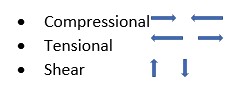
Compressional forces occur around convergent plate boundaries and lead to the shortening of the crust, while tensional forces occur around divergent boundaries and lead to an extension of the crust. Shearing forces are typically associated with transform fault plate boundaries but can be associated with spreading centres with a steplike divergent boundary. Crust is conserved; that is, it is neither extended or shortened (Figure 5.1 and Animation 5.1).
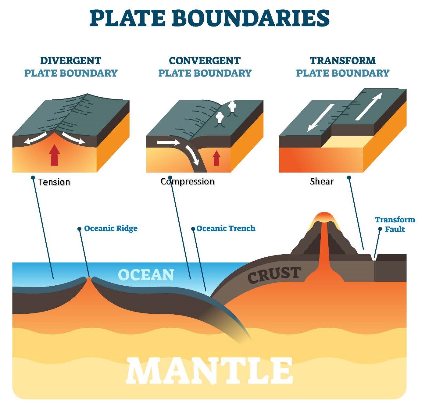
Click on the image to load the animation.
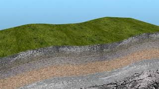
In order to observe the effect of these forces on rocks, the rocks must be exposed at the surface in an outcrop. It is from outcrops that we gather the geologic information required to identify the rock and the processes that form and deform it (Figure 5.2).
5.2 Rock Deformation
Rocks will deform in brittle or ductile manner in response to the tectonic forces acting on them. Brittle deformation means the rock cannot accommodate a force by flowing but will instead “snap,” or break. Ductile deformation means the rock accommodates a force by “flowing” instead of breaking. However, temperature also influences the nature of the rock and therefore also influences the way rocks will deform. Furthermore, the rate at which the force is applied will influence how the rock will deform, too. Let us look at this in more detail:
- Rock Type The type of rock will influence the way it deforms in response to forces acting on it. Generally speaking, if the rock is made up primarily of minerals that are hard (6 or above on Moh’s scale) and non-platy, then it will tend to deform in a brittle manner. If the minerals are primarily soft or platy, then deformation will tend to be ductile.
- Temperature Rock deeper in Earth’s crust is subjected to higher temperatures than rock that is shallower. As a result, the deeper rock is in the crust, the more it will behave in a ductile manner in response to an incident force. That means that a particular rock could deform in a brittle manner closer to the surface but the same rock could undergo ductile deformation deeper in the crust, where it is hotter.
- Deformation Rate The rate at which force is applied will also influence whether the rock will undergo brittle or ductile deformation. The faster force is applied, the greater the likelihood of the rock breaking in a brittle fashion, while a slow application of force can allow the rock to deform in a ductile manner. For example, wood is brittle at room temperature and tends to break if a large force is applied quickly. However, wood can be bent into curved shapes for construction purposes through a process that requires slow application of force to encourage bending and prevent breaking.
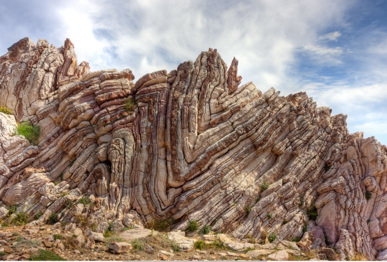
Ultimately, it will be the net effect of all three controlling factors that will determine whether a particular rock will deform as a brittle or ductile solid (Figure 5.3).
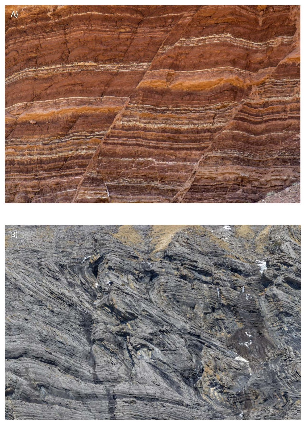
(a) Fault lines indicating brittle deformation of sandstone layers. (b) Rock layer folding indicating ductile deformation
5.3 Mapping Geologic Deformation Structures
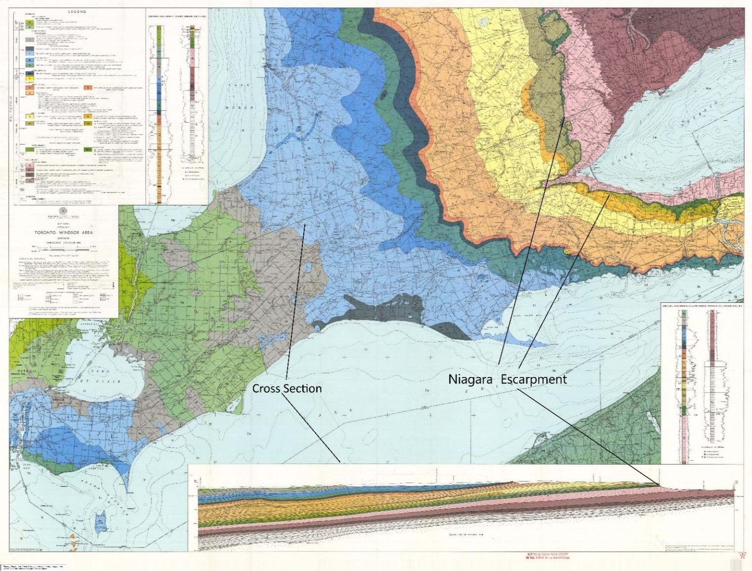
Rocks exposed in outcrops at Earth’s surface are used to infer the lateral and vertical extent of rock formations. The geologic information and the inferences are recorded on a geologic map. Furthermore, the geologic map can be used to create a geologic cross–section (Figure 5.4), which shows what the rocks would look like if you were able to cut a slice through Earth’s crust like a red velvet layer cake.
Deformation information is also collected from outcrops and displayed on geologic maps because this information is import to understanding the forces that acted on the rock as well as the sequence of events leading up to its present morphology. Specifically, because, a particular event will create deformation structures with similar orientations, the orientation of the deformation structures give clues to the sequence of deformation events. Therefore, it is possible to work out how many episodes of deformation occurred and in what order.
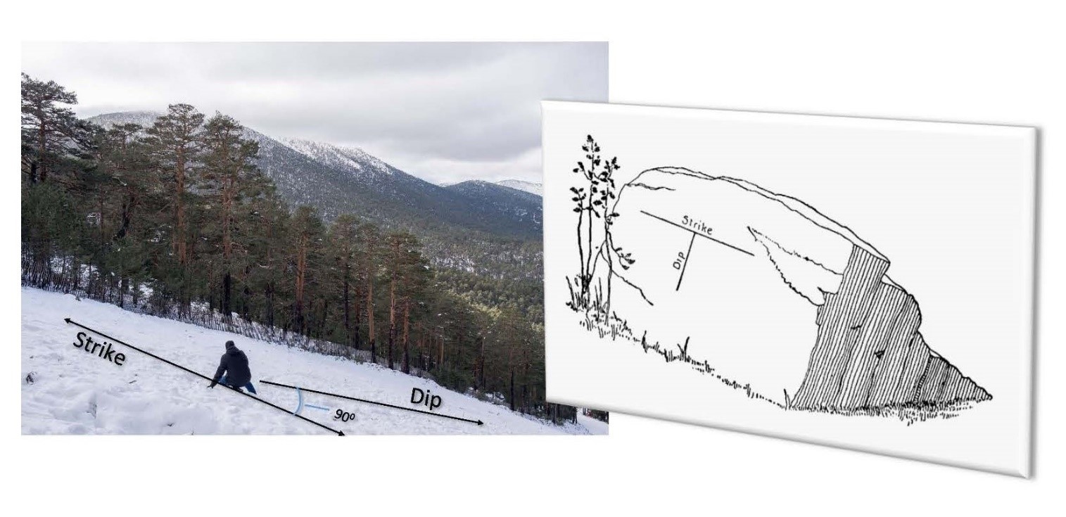
The orientation recorded for deformation structures is given in terms of the dip and the strike (Figure 5.5). The dip is the orientation of the bedding planes, fault planes, and/or fold axes of the rock from a horizontal (0°) to a vertical (90°) position. It is a measurement of how tilted to the horizontal these planes are. Another way to look at this concept is to consider how when you are skiing down a hill, you will reach maximum speed when you travel along the path of maximum dip. Skiers alternately travel along paths tangential to the maximum dip in order to control their speed and maintain control (that is the side-to-side motion you see them do).
The strike is perpendicular to the dip (that is, maximum dip) and is recorded in degrees of measure in the horizontal plane, according to a compass. That is, the orientation of the line that is perpendicular to the strike will be given as either an azimuth or a bearing. Another way to look at this concept is to consider how when a skier wants to stop moving downhill altogether, she orients herself perpendicular to the dip (slope). If she looks in the direction she is facing, she is looking along the strike. If she takes out a compass and points it in the direction she is looking, the strike would be given as the compass direction relative to north (read in a clockwise manner).
5.4 An Introduction to Deformation Structures
Deformation structures are placed into two categories based on whether their response to tectonic forces will be as a brittle or a ductile solid.
Brittle Deformation Structures (Faults)
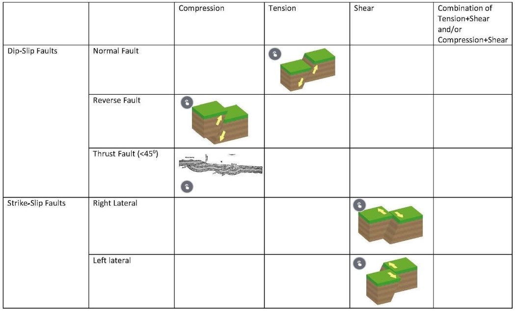
Rocks that deform in a brittle manner will develop planar cracks along which movement occurs; these cracks are called faults. There are three main types of faults as follows (see also Table 5.1):
Dip-Slip Faults
Dip-slip faults are those in which movement occurs along the dip of the planar crack. The planar crack or fault plane will “split” the layers of the rock at an angle, with the layers beneath the plane being the footwall and the layers above the plane being the hanging wall.
In response to compressive forces, the hanging wall will move up in relation to the footwall, causing a shortening of the crust. This is a reverse fault[DEF = a fault in which the crust is shortened]. When the fault plane has a shallow dip (less than 45°), the reverse fault is a thrust fault.
In response to tensional forces, the hanging wall will move down in relation to the footwall, causing an extension of the crust. This is a normal fault.
Strike-Slip Faults
A strike-slip fault is a fault in which movement occurs along the strike of the fault plane and the crust is neither extended nor shortened (that is, the crust is conserved). An example of this type of fault is the San Andreas Fault in California.
Strike-slip faults can be further classified as left lateral or right lateral based on their relative movement. A left lateral strike-slip fault is one in which rock layers on one side of the fault plane move to the left relative to the viewer. A right lateral strike-slip fault is one in which rock layers on one side of the fault plane move to the right relative to the other. Imagine you are an observer on one side of the fault looking at a tree on the other side; over time the tree will seem to move to your left, and if the tree had eyes it sees you move to its left! That makes the fault left lateral. The San Andreas Fault is a right lateral strike-slip fault.
Oblique Slip Faults
Oblique slip faults are those that occur in response to a combination of compressive and shear or tensional and shear forces. This yields a movement of rock layers on opposite sides along the fault plane diagonal to each other.
Table 5.1. Types of brittle deformation. Click on the types to see the result.
Ductile Deformation Structures (Folds)
When rocks respond to incident forces in a ductile manner, folds are created in the rock layers. These folds are defined by a fold axis that separates two limbs on either side of the axis, with the upward fold called an anticline and the downward fold called a syncline . Due to erosion at the surface, anticlines can be recognized by the exposure of older rock layers at the centre of the fold and of the youngest rocks in a syncline.
Folds develop due to compressional forces associated with convergent plate boundaries. When seen in igneous rock, folds usually indicate deep crust conditions at the base of mountain ranges associated with episodes of orogeny (mountain building).
Types of folds include the following:
- Symmetrical folds These result in anticlines and synclines
- Asymmetrical folds These have one limb that has a steeper dip than the other.
- Overturned folds These occur when both limbs dip in the same direction. This condition exists when the fold axis dips at an angle less than 45°.
- Plunging folds Both symmetrical and asymmetrical folds can plunge. The plunge is defined by fold axis that dips along the axial plane. This creates an effect of the fold “disappearing” and “plunging” beneath the surface. If the older rocks are in the centre of the fold, then the fold is a plunging anticline; if the youngest rocks are at the centre, the fold is a plunging syncline.
Asymmetrical and overturned folds indicate that there were unequal compressional forces acting on the rock layers, and plunging folds indicate another episode of deformation (Figure 5.6).
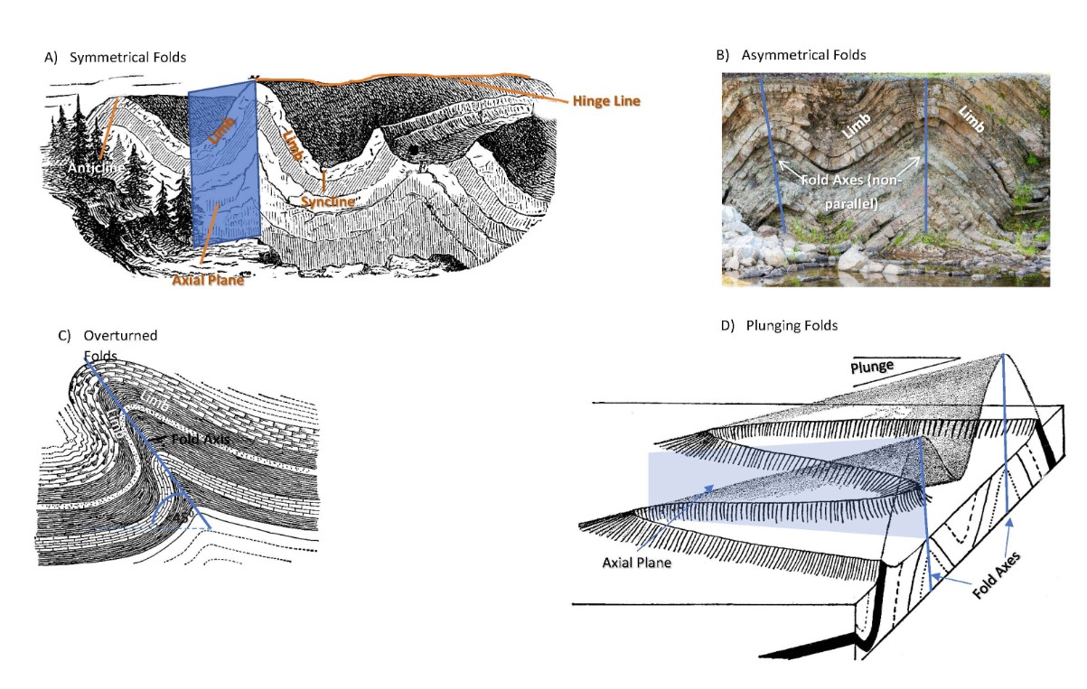
(a) Symmetrical folds. (b) Asymmetrical folds. (c) Overturned folds. (d) Plunging folds
Circular Deformation Structures
In response to compressional tectonic forces, large sections of the crust undergo upwarping or downwarping; as a result, folds may take on circular forms. When the crust is upwarped, it forms a dome that is then exposed to weathering and erosion, revealing older rocks at the centre. Downwarping of the crust creates basins, which, when eroded, reveal younger rocks at their centre. (See Figure 5.8.)
An example of a dome is the Half Dome in Yosemite National Park; one example of a basin is the Michigan Basin centred around the Upper Michigan peninsula (Figure 5.7).
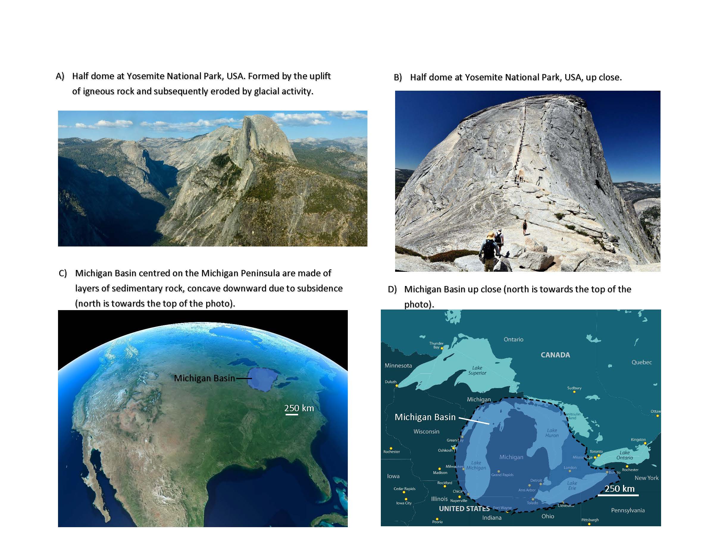
(a) Half dome at Yosemite National Park, USA; formed by uplift of igneous rock and subsequently eroded by glacial activity. (b) Closer view of the half dome. (c) Michigan Basin, centred on the Michigan Peninsula; made of layers of sedimentary rock concave downward due to subsidence (north is toward the top of the image). (d) A closer view of Michigan Basin
Other Deformation Structures
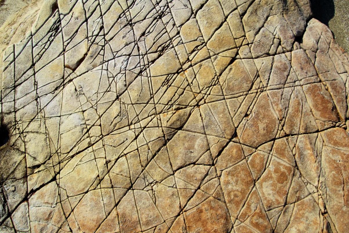
Compressional forces associated with convergence and uplift leave imprints on the rock layers other than faults and folds. These imprints manifest in the rock as planar cracks that have similar and/or related orientations and that are called joints (Figure 5.8). By mapping the orientation of sets of joints, it is possible to determine the number and order of deformational events that unfolded upon these rocks.
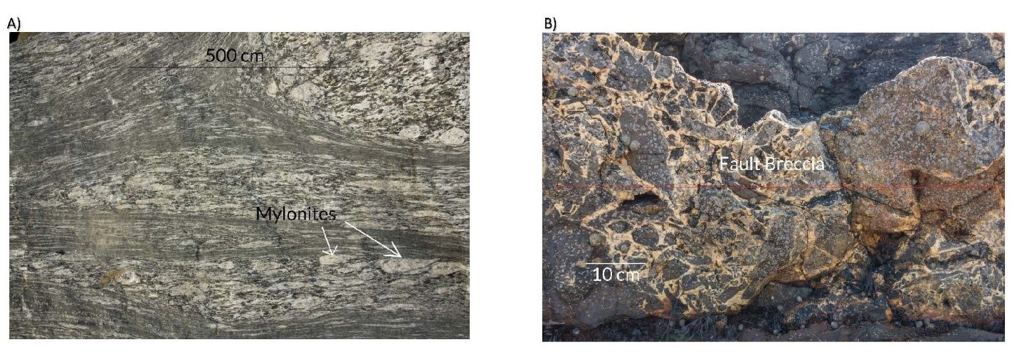
On a smaller scale, the forces acting on the rock can leave its imprint on the minerals with cataclastic textures (from the Greek kata, “down,” and klasis, “breaking”; Figure 5.9). One such texture is mylonite, in which minerals are almost pulverized due to the intense shearing associated with the compressive forces in folding and faulting. At the mineral scale, the edges of the mineral are broken up and twisted in the direction of the compressive force.
Along the fault plane, the rocks at the base of the hanging wall and at the top of the footwall are in motion past each other. This can cause pieces of various sizes to break off and become recemented by minerals precipitated by superheated water percolating through the fault. This called a fault breccia (Figure 5.9).
On a macroscopic level, tectonic deformation can define the large-scale landforms of a region (Figure 5.10). At a convergence zone, faulting and folding occurs in rock, creating mountain ranges. An example of this is the Himalaya Mountains, which are formed by continental plate collision resulting in thrust faults (low-angle fault planes). It is the relative movement of the rock layers on the hanging wall that causes the “growth” of the mountain. These periods of growth are announced by earthquakes caused by the movement.
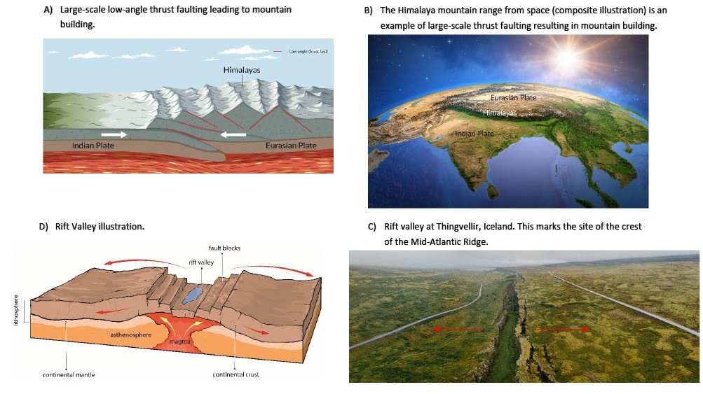
(a) Large-scale low-angle thrust faulting leading to mountain building. (b) The Himalaya mountain range from space (composite illustration), a result of large-scale thrust faulting. (c) Rift valley formation. (d) Rift valley at Thingvellir, Iceland, site of the crest of the Mid-Atlantic Ridge
At divergent plate boundaries where continental crust is separating, high-angle normal faults dominate, creating a step-like pattern on either side of the spreading centre. This creates a rift valley, or graben (Figure 5.12). A horst can be created instead of a valley if the separation occurs around a stable centre of rock layers such that the normal faults occur on either side, leaving a raised portion (Figure 5.10).
Along a transform fault plate boundary, the rocks on either side of the fault slide past each other, conserving continental crust. However, small-scale mountain ranges and rifting can occur as a result of the combination of relative motion and bending in the fault. From a bird’s-eye view, bends in the transform fault can result in the formation of mountains. For instance, if the fault has right lateral movement, compression would dominate and mountains would be created in the left bend. Rifting would occur in the right bend because tension would dominate (Figure 5.11).
Created using Google Earth
A change in dimension of a solid material
That portion of rock exposed at the surface of Earth
The physical shape of a rock or landform due to large-scale processes that were incident on it
A measurement of the tilt to the horizontal of bedding planes, fault planes, and fold axes of rock
A measurement of the compass orientation of bedding planes, fault planes, and fold axes of rock
An angle less than 90° as defined within a quadrant with cardinal directions
An angle between 0° and 360°
Planar cracks in deformed rock along which movement occurs
Faults in which movement occurs along the dip of the planar crack
Layers of split rock beneath the plane in a fault
Layers of split rock above the plane in a fault
A reverse fault in which the fault plane has a dip of less than 45°
A fault in which the crust is extended
A fault in which movement occurs along the strike of the fault plane and the crust is conserved
A fault characterized by movement of the layers on one side of the plane to the left
Faults characterized by movement of the layers on one side of the plane to the right
A fault characterized by movement of rock layers on opposite sides of the fault plan diagonal to each other
A shaping of rock layers with an axis between limbs
The upward fold in a rock layer
The downward fold in a rock layer
The dip of a fold axis in the Earth crust along the axial plan
A shaping of the Earth crust like an inverted bowl
A depression in the Earth crust
Planar cracks with similar and/or related orientations
A texture of rock in which minerals are almost pulverized
Rock created from fragments along a fault
A depression caused by a series of normal faults resulting in a rift valley
A raised section of rock between normal faults